Announcement

Collapse
No announcement yet.

Basic Soldering

Collapse
X
 
  • Filter
  • Time
  • Show
Clear All
new posts
  •  

    Basic Soldering

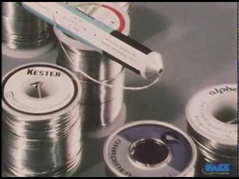
    Basic Soldering Lesson 1 - "Solder & Flux"


    Lesson 2 - "Soldering To PCB Terminals"


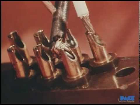
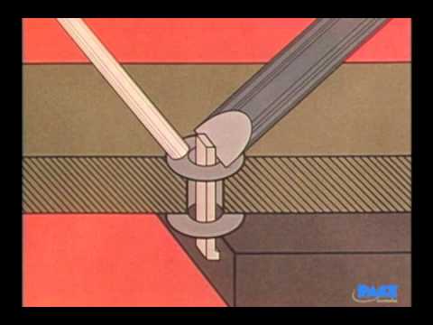
    Lesson 3 - "Cup Terminals"


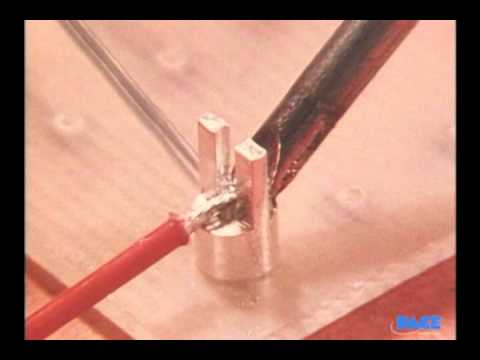
    Lesson 4 - "Bifurcated Terminals"


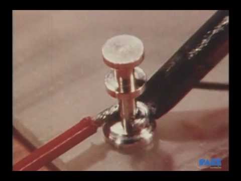
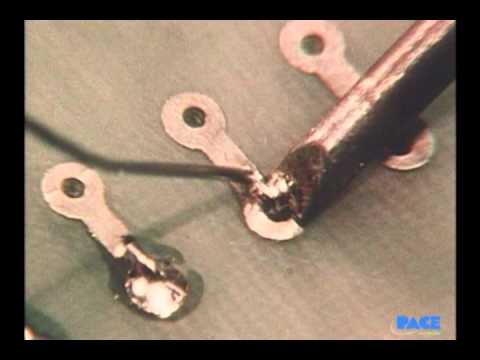
    Lesson 5 - "Hook and Pierced Terminals"


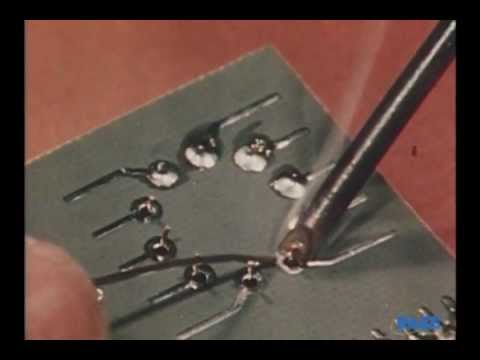
    Lesson 6 - "Component Soldering"


    Lesson 7 - "Integrated Circuits: The DIP-Type Package"


    Lesson 8 - "Integrated Circuits"


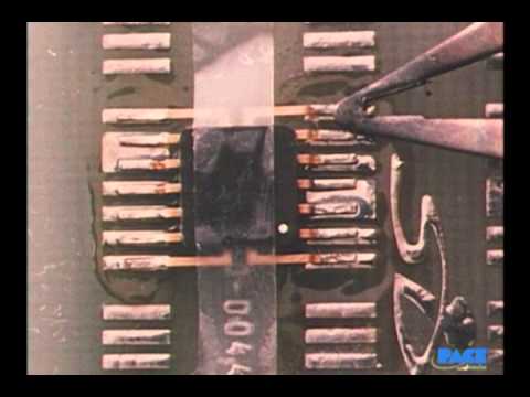
    Lesson 9 - "Integrated Circuits: The Flatpack & Other Planar-mounted Components"


    73 Al 4L5A
  •  

    #2
    Soldering Process

    Soldering is the process of joining two metals by the use of a solder alloy, and it is one of the oldest known joining techniques. Faulty solder joints remain one of the major causes of equipment failure and thus the importance of high standards of workmanship in soldering cannot be overemphasized.

    The following material covers basic soldering procedures and has been designed to provide the fundamental knowledge needed to complete the majority of high-reliability hand soldering and component removal operations.

    Properties of Solder

    The solder used for electronics is a metal alloy, made by combining tin and lead in different proportions. You can usually find these proportions marked on the various types of solder available.

    With most tin/lead solder combinations, melting does not take place all at once. Fifty-fifty solder begins to melt at 183 C -361 F, but it's not fully melted until the temperature reaches 216 C - 420 F. Between these two temperatures, the solder exists in a plastic or semi-liquid state.

    The plastic range of a solder varies, depending upon the ratio of tin to lead. With 60/40 solder, the range is much smaller than it is for 50/50 solder. The 63/37 ratio, known as eutectic solder has practically no plastic range and melts almost instantly at 183 C -361 F.

    The soldiers most commonly used for hand soldering in electronics are the 60/40 type and the 63/37 type. Due to the plastic range of the 60/40 type, you need to be careful not to move any elements of the joint during the cool down period. The movement may cause what is known as a disturbed joint. A disturbed joint has a rough, irregular appearance and looks dull instead of bright and shiny. A disturbed solder joint may be unreliable and may require rework.

    Wetting Action

    When the hot solder comes in contact with a copper surface, a metal solvent action takes place. The solder dissolves and penetrates the copper surface. The molecules of solder and copper blend to form a new alloy, one that's part copper and part solder. This solvent action is called wetting and forms the intermetallic bond between the parts. (See Figure 1) Wetting can only occur if the surface of the copper is free of contamination and from the oxide film that forms when the metal is exposed to air. Also, the solder and work surface need to have reached the proper temperature.

    Although the surfaces to be soldered may look clean, there is always a thin film of oxide covering it. For a good solder bond, surface oxides must be removed during the soldering process using flux.

    Flux

    Reliable solder connections can only be accomplished with truly cleaned surfaces. Solvents can be used to clean the surfaces prior to soldering but are insufficient due to the extremely rapid rate at which oxides form on the surface of heated metals. To overcome this oxide film, it becomes necessary in electronic soldering to use materials called fluxes. Fluxes consist of natural or synthetic rosins and sometimes chemical additives called activators.

    It is the function of the flux to remove oxides and keep them removed during the soldering operation. This is accomplished by the flux action which is very corrosive at solder melt temperatures and accounts for flux's ability to rapidly remove metal oxides. In its unheated state, however, rosin flux is non-corrosive and non-conductive and thus will not affect the circuitry. It is the fluxing action of removing oxides and carrying them away, as well as preventing the reformation of new oxides that allows the solder to form the desired intermetallic bond.

    Flux must melt at a temperature lower than solder so that it can do its job prior to the soldering action. It will volatilize very rapidly; thus it is mandatory that flux is melted to flow onto the work surface and not be simply volatilized by the hot iron tip to provide the full benefit of the fluxing action. There are varieties of fluxes available for many purposes and applications. The most common types include Rosin - No Clean, Rosin - Mildly Activated and Water Soluble.

    When used, liquid flux should be applied in a thin, even coat to those surfaces being joined and prior to the application of heat. Cored wire solder and solder paste should be placed in such a position that the flux can flow and cover the joints as the solder melts. Flux should be applied so that no damage will occur to the surrounding parts and materials.

    Soldering Irons

    Soldering irons come in a variety of sizes and shapes. A continuously tinned surface must be maintained on the soldering iron tip's working surface to ensure proper heat transfer and to avoid transfer of impurities to the solder connection.

    Before using the soldering iron the tip should be cleaned by wiping it with a wet sponge. When not in use the iron should be kept in a holder, with its tip clean and coated with a small amount of solder


    Controlling Heat

    Controlling soldering iron tip temperature is not the key element in soldering. The key element is controlling the heat cycle of the work. How fast the work gets hot, how hot it gets, and how long it stays hot is the element to control for reliable solder connections.

    Thermal Mass

    The first factor that needs to be considered when soldering is the relative thermal mass of the joint to be soldered. This mass may vary over a wide range.

    Each joint has its own particular thermal mass, and how this combined mass compares with the mass of the iron tip determines the time and temperature rise of the work.

    Surface Condition

    The second factor of importance when soldering is the surface condition. If there are any oxides or other contaminants covering the pads or leads, there will be a barrier to the flow of heat. Even though the iron tip is the right size and temperature, it may not be able to supply enough heat to the joint to melt the solder.

    Thermal Linkage

    A third factor to consider is thermal linkage. This is the area of contact between the iron tip and the work.

    Figure 2 shows a view of a soldering iron tip soldering a component lead. Heat is transferred through the small contact area between the soldering iron tip and pad. The thermal linkage area is small.

    Figure 3 also shows a view of a soldering iron tip soldering a component lead. In this case, the contact area is greatly increased by having a small amount of solder at the point of contact. The tip is also in contact with both the pad and component further improving the thermal linkage. This solder bridge provides thermal linkage and assures the rapid transfer of heat into the work.

    Applying Solder

    In general, the soldering iron tip should be applied to the maximum mass point of the joint. This will permit the rapid thermal elevation of the parts to be soldered. Molten solder always flows from the cooler area toward the hotter one.

    Before solder is applied; the surface temperature of the parts being soldered must be elevated above the solder melting point. Never melt the solder against the iron tip and allow it to flow onto a surface cooler than the solder melting temperature. Solder applied to a cleaned, fluxed and properly heated surface will melt and flow without direct contact with the heat source and provide a smooth, even surface, filleting out to a thin edge. Improper soldering will exhibit a built-up, irregular appearance and poor filleting. For good solder joint strength, parts being soldered must be held in place until the solder solidifies.

    If possible apply the solder to the upper portion of the joint so that the work surfaces and not the iron will melt the solder, and so that gravity will aid the solder flow. Selecting cored solder of the proper diameter will aid in controlling the amount of solder being applied to the joint. Use a small gauge for a small joint and a large gauge for a large joint.

    Post Solder Cleaning

    When cleaning is required, flux residue should be removed as soon as possible, but no later than one hour after soldering. Some fluxes may require more immediate action to facilitate adequate removal. Mechanical means such as agitation, spraying, brushing, and other methods of applications may be used in conjunction with the cleaning solution.

    The cleaning solvents, solutions, and methods used should not have affected the parts, connections, and materials being cleaned. After cleaning, boards should be adequately dried.

    Resoldering

    Care should be taken to avoid the need for resoldering. When resoldering is required, quality standards for the resoldered connection should be the same as for the original connection.

    A cold or disturbed solder joint will usually require only reheating and reflowing of the solder with the addition of suitable flux. If reheating does not correct the condition, the solder should be removed and the joint resoldered.

    Workmanship

    Solder joints should have a smooth appearance. A satin luster is permissible. The joints should be free from scratches, sharp edges, grittiness, looseness, blistering, or other evidence of poor workmanship. Probe marks from test pins are acceptable providing that they do not affect the integrity of the solder joint.

    An acceptable solder connection should indicate evidence of wetting and adherence when the solder blends to the soldered surface. The solder should form a small contact angle; this indicates the presence of a metallurgical bond and metallic continuity from solder to surface. (See Figure 4)

    Smooth clean voids or unevenness on the surface of the solder fillet or coating are acceptable. A smooth transition from pad to component lead should be evident.

    Comment

    Working...
    X