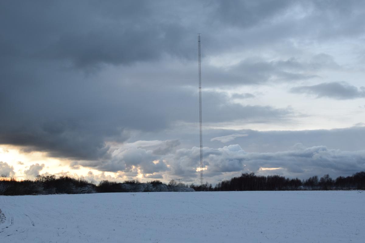
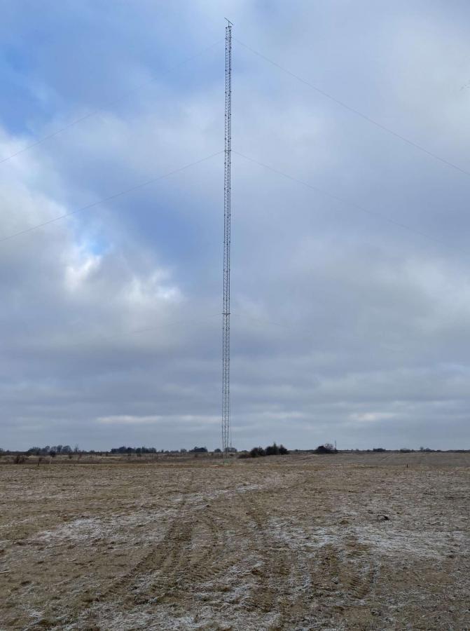
UA9BA Design 160m Spitfire antenna
The start of the project
Sergey UA2FW called me on phone one evening in late August 2020 and invited me to the group of fine operators for the CQWW CW 160m 2021 CONTEST. He also asked if I was willing to propose and design a transmitting antenna that would be as good or better than a regular 4SQ and also help out with layout of a transmitting and receiving sites on the available property. I agreed on both invitations and started to work on the antenna design.
The choice in favor of a spitfire
I won't describe in details how Sergey and I came to the decision of building a totally NEW TX/RX 160m site at UA2FW's for the CQWW 160m 2021 CW contest, neglecting already existent and fully available site with a full size 4SQ with many beverages around but defeated with inevitable man-made noise and not a very good terrain profiles in main directions. The good thing about this project was availability of lots of land (some 80 acres or so), so land wasn't a limiting factor whatsoever. In this article, though, I will rather concentrate on describing the design of transmitting antennas.
Making a choice on the type of the transmitting antenna was a rather interesting process. The limiting factors were these: from the practical stand point - we only had 5 months to design and build an effective TX antenna on 160m band - it had to be a vertically polarized antenna, the antenna must feature the ability of simultaneous transmitting in at least two directions of the operator's choice with gain exceeding that of a regular 4SQ, the azimuth pattern must cover all major target areas such as North America, Caribbean, South America, Japan and South-East Asia with Australia and New Zealand behind, Africa with Middle East and the deep Pacific Ocean.
The "must" for any two direction simultaneous transmission was the hardest feature to satisfy. Once I realized that, I came to the crucial decision - the transmitting antenna must consist of two separate antennas. The easiest and a straightforward solution to the dilemma was a pair of 4SQs. But what about gain that must exceed that of a 4SQ?
I had once built a two element vertical array with one half of wavelength separation between the elements. It was in mid 90s when we were active as RZ9AZA. We were either feeding the elements in phase or out of phase (180 deg. phase shift) and the antenna was a real killer on Top Band. Remembering that experience, knowing of the VY2ZM's approach at his magic QTH on Prince Edward Island I at one point thought of two spitfires horizontally stacked at 0.5 wavelength. I immediately got to the computer and quickly modeled the antenna. Man! Did I love the numbers! 8.5+ dBi of Gain versus 6.2+ of a regular 4SQ with reasonable front-to-back ratio exceeding 25 dB at design frequency segment. So, instantly I knew I found the solution to the task.
The spitfire antenna
In this chapter I will explain why the parasitic elements - director and reflector - were made of folded elements. Let's see what a regular spitfire looks like and how implementation of folded parasitic elements improves its performance characteristics.
We will first study performance of a typical spitfire antenna made of driven element 49.266 meters high 200 mm OD (just as it is in the erected antenna) with parasitic director and reflector both made of single wires 4 mm OD. See it on Figure 1 down below.
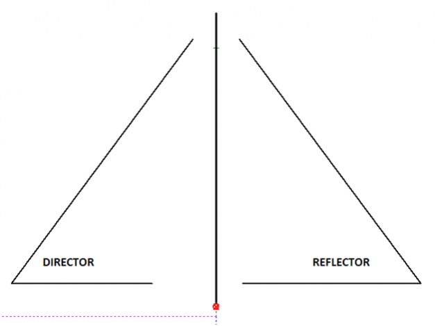
Figure 1
I optimized both antennas - classic spitfire and the folded one - within the same frequency range of 1810 kHz to 1900 kHz with the same optimization goals - input impedance of 75 Ohms and equal Front-to-Back numbers at the band edges (1.810-1.900 MHz), so we could compare their performance. The parameters of interest to be analyzed and compared were - 1.5:1 VSWR Bandwidth, Gain curve, F/B curve and patterns. See those for the typical spitfire on Figures 2, 3 and 4. (The name of MMANA file for this one is " SPITFIRE 160 REGULAR PARASITES.maa")
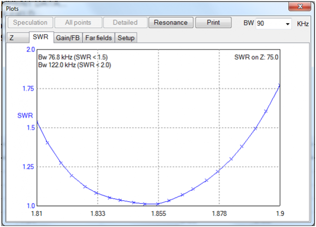
Figure 2
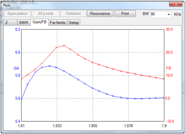
Figure 3
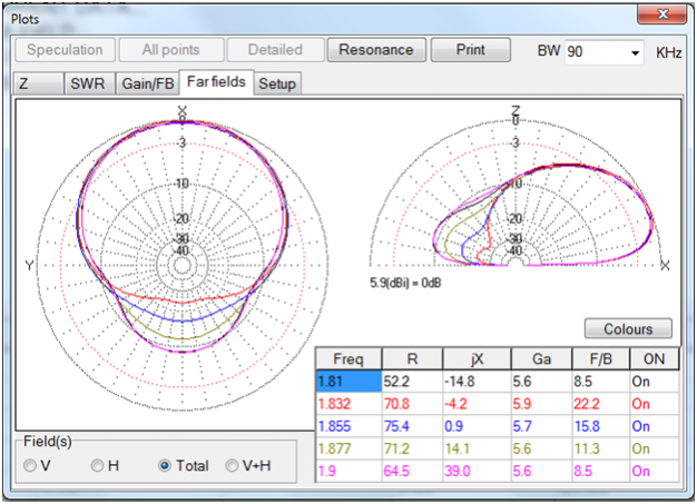
Figure 4
Well, those are pretty neat curves and numbers for such simple antenna, aren't they? But let's see on Figures 6, 7 and 8 what they look like with parasites made of folded elements with wires of 2 mm OD as shown on Figure 5. (The name of MMANA file for this one is " SPITFIRE 160 WIDEBAND PARASITES.maa").
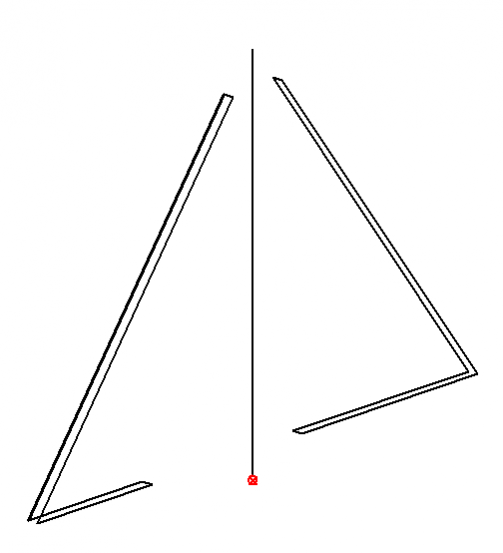
Figure 5
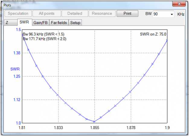
Figure 6
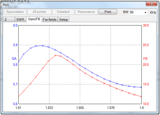
Figure 7
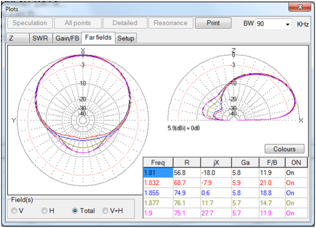
Figure 8
One can see a noticeable difference in favor of the folded parasitic elements model - the 1.5:1 VSWR bandwidth has risen to almost 100 kHz, Gain curve shows a 0.1 dB increase and the F/B is also higher at the edges of the frequency range by more than 3 dB within the band. So, this superiority was the reason why I had chosen the folded type of parasites for the spitfire.
Stacking two spitfires side by side
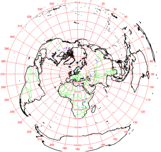
The stacking distance was an easy case. I knew from the books that for two element frames with antennas fed in phase the compromise between clean main lobe pattern with minor lobes under 13 dB and highest gain was laying within 0.65 -0.75 wavelength of spacing. And indeed! The MMANA modeling shows a 9.3 dB of gain with -3dB beam width of 41 degrees at spacing of 0.75 wavelength. Those are great numbers! But on the other hand, for instance, the foot print of USA from Palm Beach FL. to Seattle WA. is seen from Kaliningrad (UA2F) within segment of azimuth angles of 41 degrees. And we know that working USA on Top Band from Eastern Europe is a very challenging task, so, every 0.1 dB counts.
Azimuth World Map centered at UA2FWs
So, I just made a decision that the spacing will be 85 meters. Not 95, not exact half wavelength of 82+ meters, just 85. The -3 dB beam width with that horizontal spacing between the two spitfire antennas is 55 degrees with gain figure still showing a high number of 8.6+ dB. See the pattern on Figure 9 below.
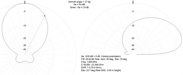
Figure 9
Actually, this pattern is very similar in azimuth plane to that of a 5 element 20 m yagi on a short 12.5 meter long boom. This fact really got me when I'd discovered it while working on this project. Isn't it really amazing!
And yet, if we pointed such an antenna right into the middle of the USA foot print the states of Florida and Washington would receive 1.7 dB less power from the antenna than the Mid West states and that would've been absolutely unacceptable situation, at least as far as I am concerned. Then I just thought of HF band operations with highly directive antennas where an op must rotate the antenna like crazy for the whole period of a contest. So, why not use same technique on Top Band, but with phased two element array that can be electronically scanned over a limited range of angles. I liked that idea and we implemented this feature in the antenna. See the patterns on Figure 10.
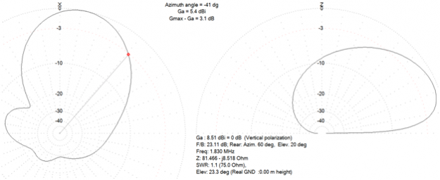
Figure 10
As one can see the main lobe gain at its peak, when tilted by 13.5 degrees is only 0.15 dB down from the "in phase" position and is, making a -3 dB point appear at 41 degrees, thus making overall beam width of the array a respectable +/- 41 degrees or a total value of 82 degrees. Now the Florida and Washington stations will only suffer a 0.3 dB of signal strength loss when compared to Mid West stations. Now I was ready to accept it as a good compromise.
Practical design of a two element collinear spitfire array at UA2FW
You can see the antenna with some dimensions shown on Figure 11. This is the drawing of the "SPITFIRE COLLINEAR ARRAY" installed in quantity of two - one for azimuth angles 305, 125 the other one for 65, 245 - at UA2FW specifically for the CQWW CW 160m CONTEST 2021.
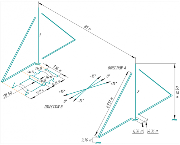
Figure 11
I must explain the chosen height of the center driven element of 49.266 meters. This height ensures higher values of active part of the input impedance of the antenna, thus making it more efficient minding the ground losses, yet presenting a rather small positive reactance at the base which is easy to compensate with practical value capacitors of reasonable reactive power handling ability (we did the job with the ceramic ones, so no expensive vacuum ones - nicely looking attractions for thefts - were needed). The MMANA file for the array that was installed is named " 2 x 3el gp160 for cqww 160 2021 @ ua2fw's FINAL.maa". You can extract all the dimensions from the file. The performance curves and numbers of the antenna can be seen on Figures 12, 13, 14, 15.
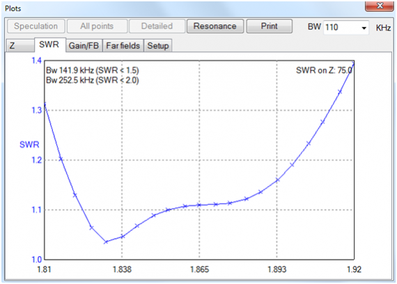
Figure 12
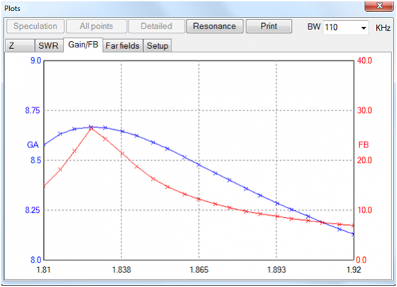
Figure 13
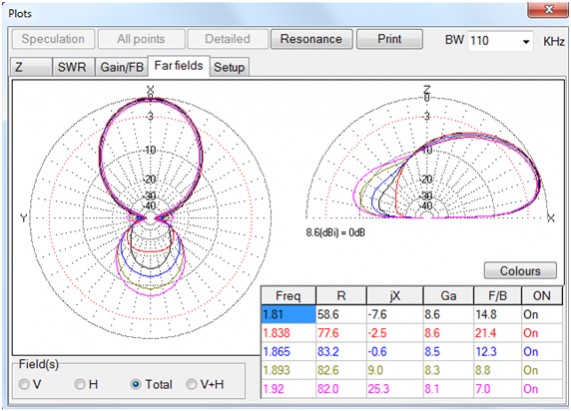
Figure 14
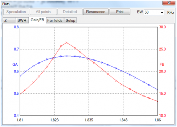
Figure 15
Pattern control switch box circuit diagram can be seen on Figure 16 and truth table for the whole array is shown on Figure 17.
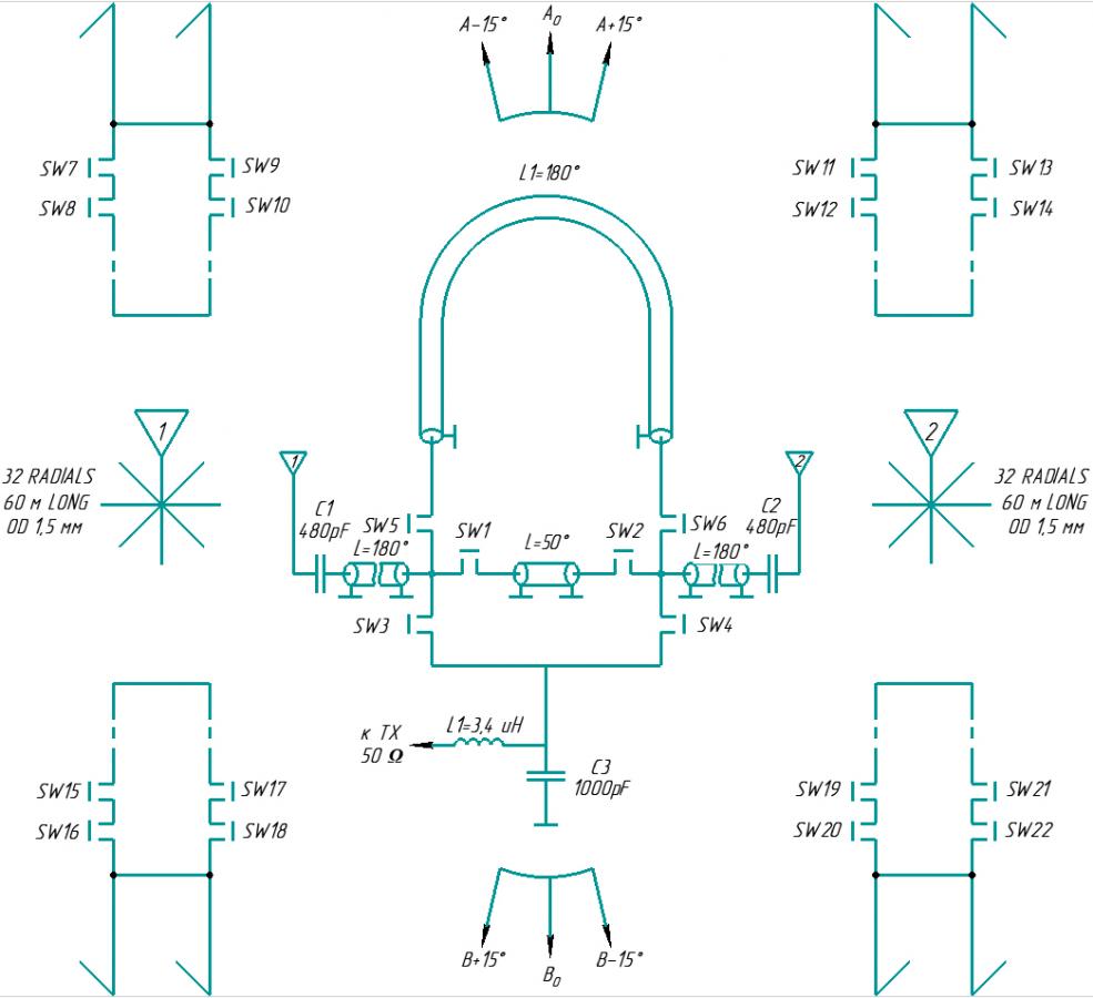
Figure 16
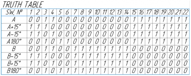
Figure 17
When “A 180°” is activated then we have a two lobe pattern like on Figure down below with very respectable Gain numbers of 6.1 dBi. Button “B 180°” would flip the lobes the other way around.
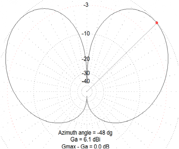
Figure 18
Don't fool around with steel guy wires broken by ceramic insulators
Once the array was up and running (Monday, Jan. 25th 2021 i.e. 4 days before the contest start) I being at my Ural Mountains home and Sergey UA2FW together with Vladimir RU2FJ on the transmitting antenna site in Kaliningrad did on the air test. I wanted to see if the deep Front-to-Back frequency range was in its place 1.810 - 1.850 MHz and additional adjustment of the parasitic elements wasn't needed. Boy, was I disappointed with the performance of the collinear array! The F/B ratio didn't go higher than 1.5 S-unit on my K3 with signal from UA2FW of s9+10 dB (The TX they had at the time was FT2000 at 200 Watts output) on any frequency of the band. That was really bad news. It took me some hours to try to figure out where the mistake had occurred. I finally thought of the guy wires for the parasites at the tops of the 49m towers, at the angles 3.76 meters above ground and at the lower ends of parasites. All these guy wires were made of steel wires 5 mm OD each wire with two ceramic insulators at both ends. The longest wires were keeping the upper ends of parasites to the tops of tower and they measured 7 meters in length - less than 0.05 wavelength. I have had written but never published an article on bad effects of steel guy wires with insulators on performance of the antennas. I hope one day I will make up my mind to finish that article. In any way to mare a long story short I modeled the guy wires (I knew the values of leakage capacitances of the insulators Sergey used) and was amazed at the patterns I saw on the screen. See it on Figures 18 and 19.
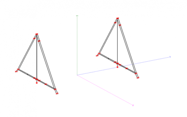
Figure 19
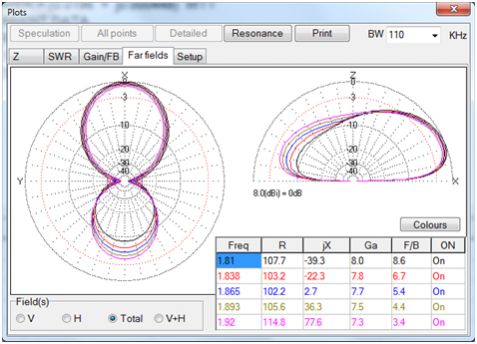
Figure 20
The guy wires ruined vital characteristics - Gain, F/B, Input Impedance. that was more like a disaster! I had to make a difficult decision 3 days before the contest. Leave the array as is with almost 1 dB lower Gain numbers and operate it under handicapped condition or tell Sergey to call on the tower guys and order them to replace the steel guy wires with Kevlar type ones, which was an extra expense and another day and a half of delay in final adjustment of the two arrays. So, I told Sergey to replace the guy wires. And he did so, and the numbers got to where they belonged! We did the final fine tuning of the arrays hours before the contest started. So we didn't even do the smoke test. It was our good luck, there was no smoke in the arrays' guts nowhere throughout the contest and it performed very well producing a loud signal in far away destinations with modest power from OM amp shared by the two arrays.
by Vladimir (Willy) Umanets UA9BA from Karataban of Chelyabinsk oblast on February 4th 2021
SPITFIRE 160 Regular Parasites
SPITFIRE 160 Wideband Parasites
2x3 gp160 for CQWW 160 2021 @UA2FW Final
Photo gallery
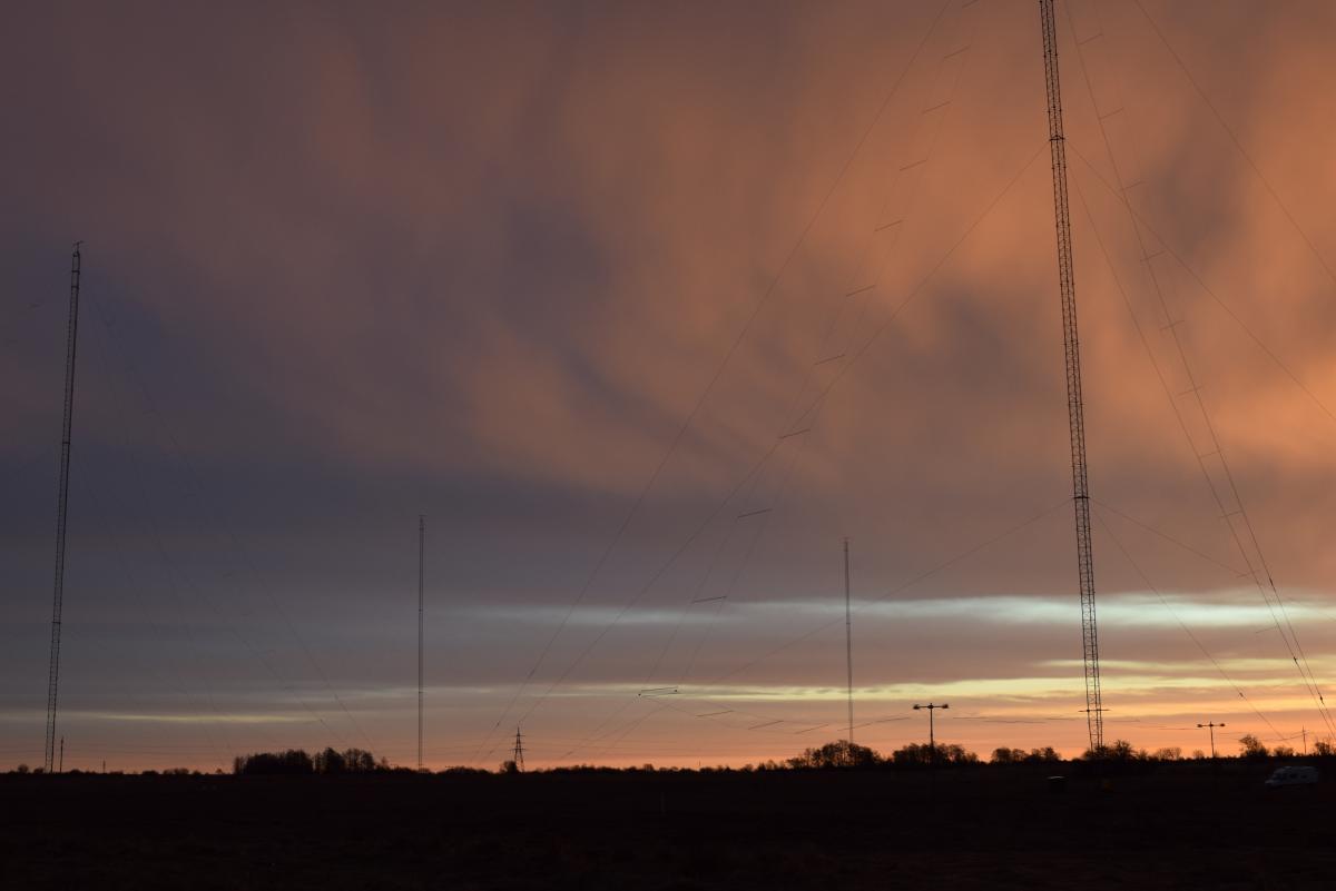
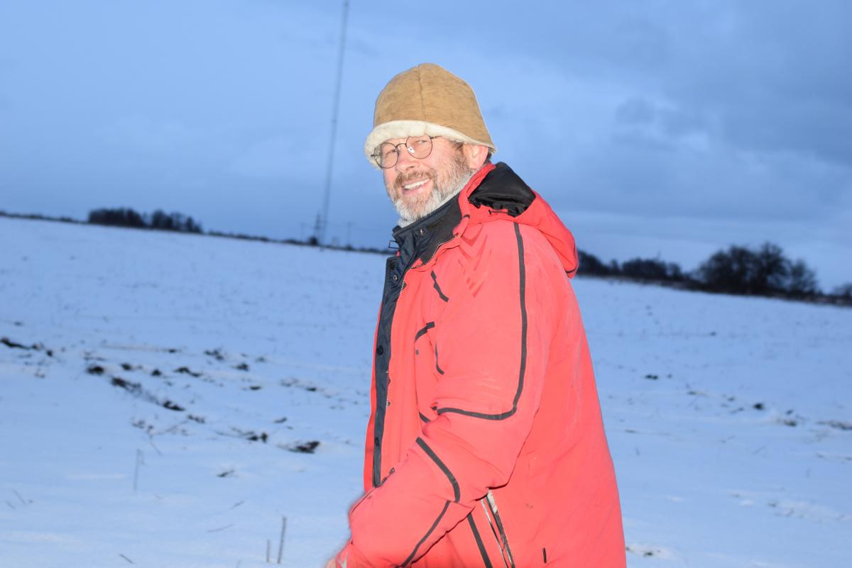
Sergey Shikhotarov, UA2FW
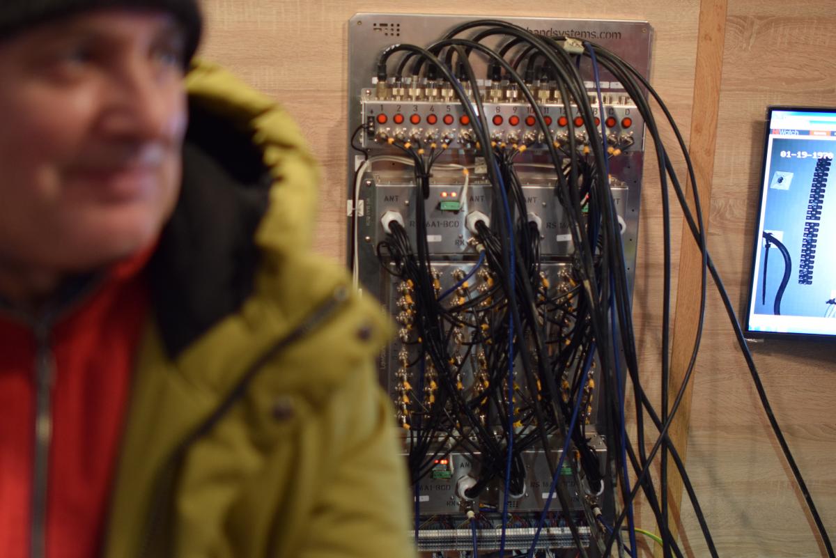
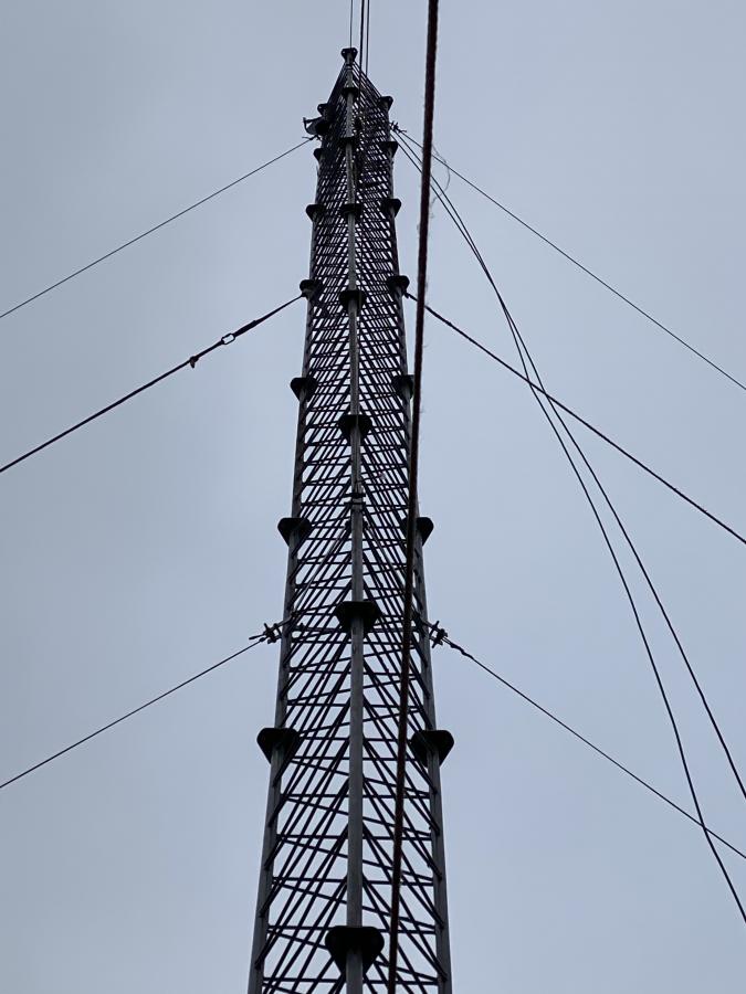
49.2m tower
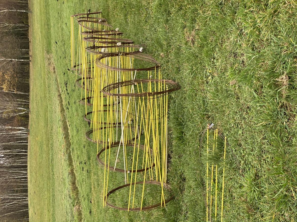 Parasites waiting their turn to go up the 49m tall towers
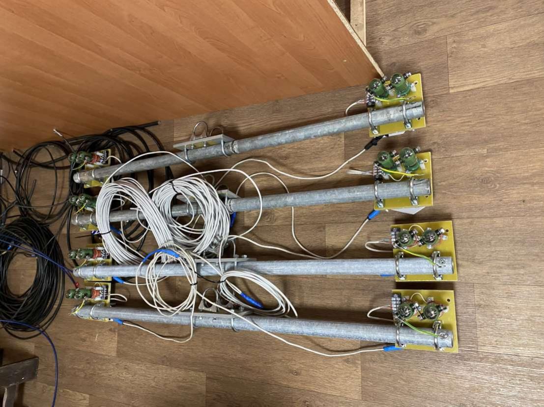 Reflector-Director switch boxes
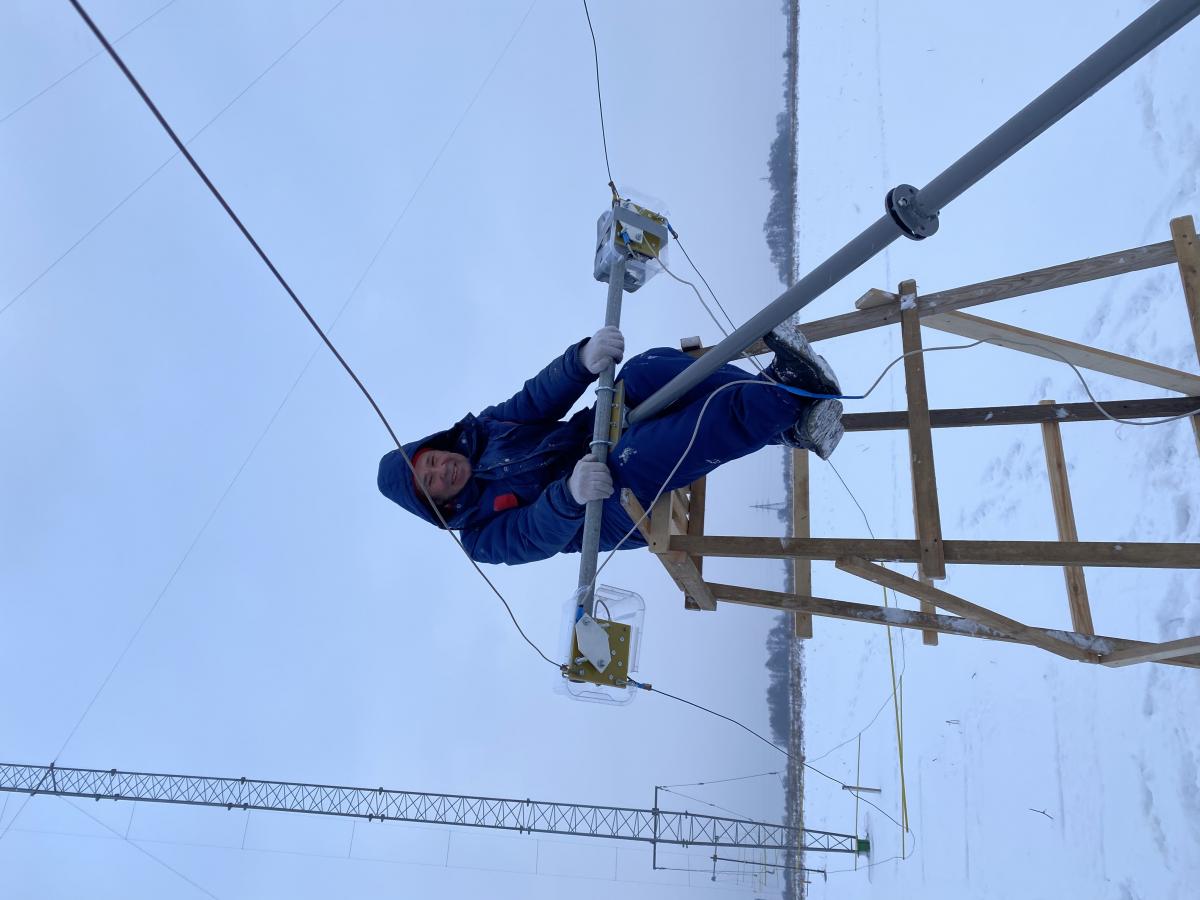 RT2F about to install Reflector -Director switch box pole
Tower alone no parasites
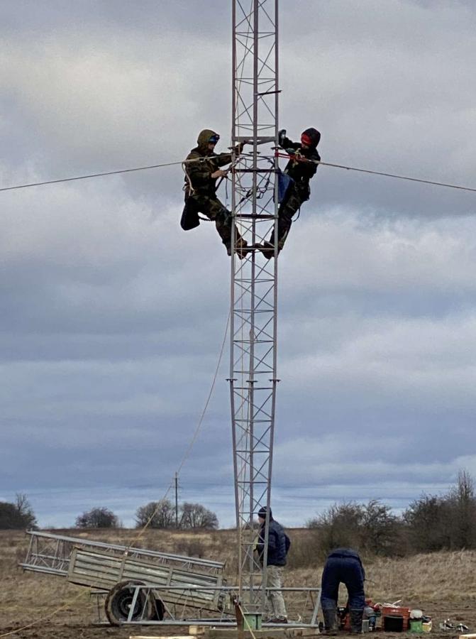
Tower team at work

