It is a common practice these days using vertically stacked directional antennas, in particular yagi - udo type. The effect of vertical stacking was very well described by James Lawson W2PV in his historical "Yagi antenna design" book. In short the main effect is in combining radiated (received) energy from all vertical lobes into one, thus getting extra gain. Another effect of vertical stacking is not only obtaining extra gain but also widening in vertical plain the main lobe. See Fig.1 as an illustration of the two effects mentioned above.

Figure 1.
The azimuth and vertical plane plots show the patterns of single 7 element 20m yagi at 42 meters high (black lines) and two such yagis vertically stacked at 42 and 21 meters (red lines). The stack is actually in current use at UP2L.
In this article I will be using some material available on the site of K3LR ( WWW.K3LR.COM ) with Tim's kind permission. Why K3LR? Because it's one of the few professionally engineered world rank contest stations with lots of technical data available on the site that can be easily referred to.
Big contest stations use stacks for their advantage over single antennas by varying combinations of available stacked antennas. For instance, K3LR uses up to 10 different combinations on all 4 layer stacks 20 through 10 meter bands http://www.k3lr.com/Hardware/. So, the operator at the controls can switch between 10 combinations to find the best one for particular path at particular time. Quite a challenge, huh? These 10 combinations allow the operator to tilt the main lobe in vertical plane from the lowest possible (the upper antenna alone, the two upper or the three upper antennas) to the highest possible (the bottom two, the three bottom) positions.
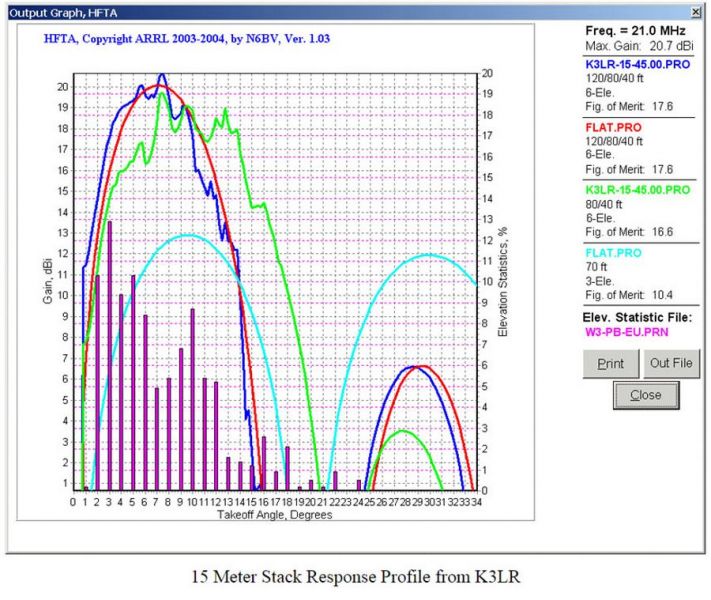
At the same time we all know that the farther the destination of communication point the lower the most usable angles, both take-off and arrival. The opposite is true for short range communications - the higher angles are most suitable. Since contesting is about making the highest possible number of long distance QSOs I will only deal here with use of stacks for long range QSOs (2500+ km). Now the question is - what is practical range of vertical angles for long distance communication. A good answer can be found on the site of K3LR at http://www.k3lr.com/engineering/15m_stack.htm

Figure 2.
The pink bars in Fig.2 show that angles of arrival vary from 1 degree to 24 degrees with two major peaks - at 3 (13%) and 10 (8.7%) degrees. We can also conclude that only 10 percent of signals from Europe come in at Tim's location on 15 meter band at angles higher than12 degrees. The blue curve of stack
response of three 6 element yagis stacked at 120/80/40 feet embraces the pink bars most efficiently, even though there are some signals left out at angles higher than 15 degrees. What else is important is the second blue lobe peaking at 28.5 degrees of significant strength - 13 dB down from the main lobe. The energy contained in that lobe is 100% wasted on this particular path. The way to accommodate the left out higher angles above 15 degrees is to switch to lower two antennas (the green curve), but with that combination operator loses almost 5 dB of gain at most important low angles from 2 to 4 degrees where 32.5% of all QSOs come from!
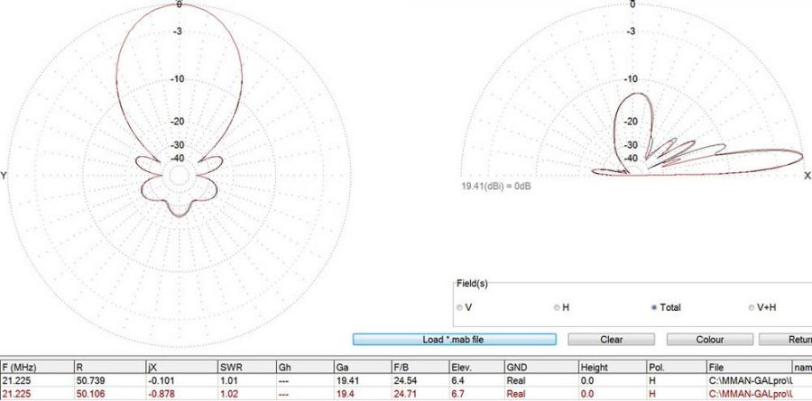
Now, let's look at what uneven amplitude and phase distribution (UAPD) of available energy among stacked antennas does to the pattern in the vertical plane. I modeled a stack of three 6 element 15m monobanders on 14 meter booms on 35,57 meter tall tower (120 feet) equidistantly spaced over flat average ground (conduct. 7 mS/m, dielect. const 7) fed in phase and with equal power in one case (red lines) and fed in a special way of UAPD in other case (black lines). You can see the comparison of the two in Fig.3 down below .

Figure 3.
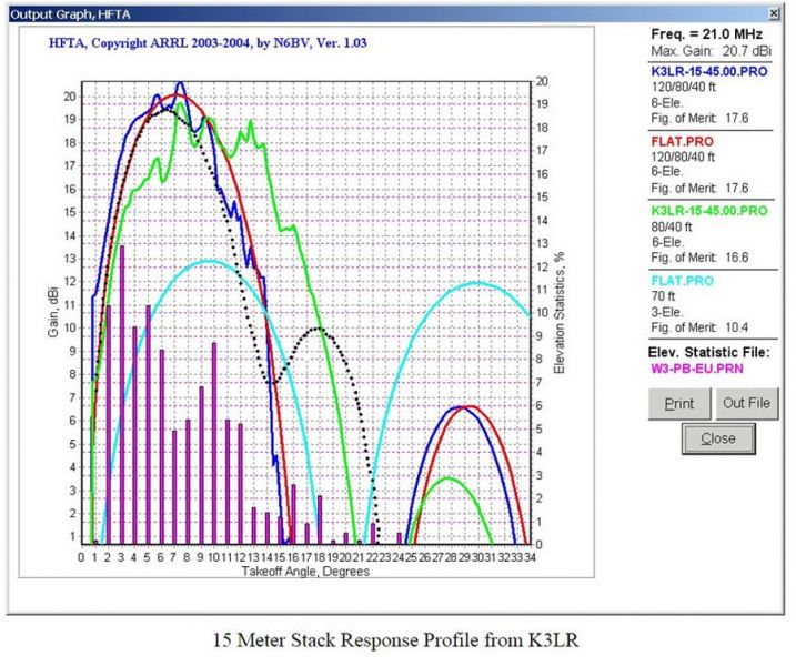
The patterns with identical gain look similar, but there’s a significant difference there. To feel the difference better I interposed the black lined pattern with UAPD feeding on K3LR’s plot of Fig. 2. The result is shown on Fig.4 down below. My model lacks some 0.6 dB of gain compared to K3LR’s array but that’s of no importance in this case. The important thing is – there’s no deep null in pattern at workable angles anymore! The black dotted pattern covers all workable angles with positive gain whilst the main lobe gain remained as high as if the stacked antennas were fed in conventional way - in phase and with equal power to each antenna.

Figure 4.
Another effect worth mentioning is a slight tilt down to the horizon of main lobe peak. As can be seen from the Fig.2 numbers in the table the main lobe peak of conventionally fed stack peaks at 6.7 degrees and the UAPD one peaks at 6.4 degrees.
In this particular example of unevenly fed stack of three 6 element 15m yagis at 120/80/40 feet the power distribution was 50% to the top antenna, 33.4% to the middle one and 16.6% to the bottom ant. Numbers may look weird, but the reasons for such distribution is simple – one half of power goes to the top, the other half goes to the bottom two and between the bottom two the middle antenna gets twice the power of the bottom one. Such proportion is easily accomplished through use of a series-parallel combination of quarter wave transformersmade of regular 50 and 75 Ohm coaxial lines (I will deal with it later in more details). The phasing was 40 degrees to the bottom, 25 degree lag to the middle and 0 degree lag to the top. These numbers may vary. For instance there’s a combination that leads to a .15 dB of gain over conventionally fedstack, so it is up to the designer to decide what numbers suit best the design goals. I just wanted to share this information with fellow amateurs. As of today this UAPD is implemented at RM9A, RK9AX and some other big gun stations in
Russia going through the construction phase at the moment. The users say that there’s less QSB on the signals and they seem to hear more people now. I will come up with one more article on this feeding method with attention to more hardware details.
By Vladimir (Willy) Umanets UA9BA Chelyabinsk Russia Dec. 2015
 https://dxnews.com

